Key Framed Animation Part 2
In Part 1 we discussed the basics of key framed animation. In part 2 we will begin to discuss how key framed animation is implemented and controlled in Toon Boom Studio.
Pictures are composed of multiple picture elements
As we all discussed in It's Elemental Part 1, animation is created by rendering a series of pictures in a sequence and displaying those pictures at a sufficient rate of speed so as to generate the phenomena called “persistence of vision”. Basically our goal is to optically blend sequential images together to create the visual effect of continuous motion. The individual pictures themselves can be a single element or a combination of many picture elements. In most animations, the pictures in the sequence, also referred to as the frames in the sequence, are constructed as compositions of many layered picture elements. In traditional hand drawn animation, these picture elements are arranged in an overlapping layered stack under a rostrum camera for photographing.
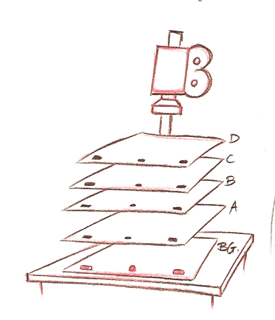
Each picture element traditionally was created separately on a clear transparent plastic sheet called a cell. The stacking order of the cells creates the visual effect of depth by allowing some picture elements to overlap other picture elements producing perspective in a 2D picture. In order to position each picture element’s cell relative to the other elements of that composite picture, there is the need for some means of element registration. The accurate registration of picture elements to avoid unintentional shifting is critical because any variation in the positioning of a picture element photographed in successive frames of an animated sequence creates the illusion of motion. To accomplish this accurate positioning, a cell registration device had to be invented, and thus the registration peg and the registration peg bar were created. By punching registration holes in each cell that matched the registration peg pins of the peg bar, it was possible to insure accurate positioning of each and every drawing element in the layered composition stack for each photographed frame of the animation. Additionally by utilizing multiple peg bars, some which were held stationary and some which could be incrementally repositioned, it became possible to create the illusion of motion by simple frame by frame repositioning of selected image elements. These incrementally movable peg bars became known as traveling peg bars.
Click on image to view full size
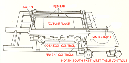
Besides having multiple traveling peg bars, a photographic animation camera stand also has an incrementally movable picture composition surface, the picture plane, that is capable of producing compound movements in all horizontal directions (North, South, East and West) including 360 degree rotational movements. The creation of the multi-plane camera stand, by the addition of multiple picture composition planes, provides additional photographic depth between picture elements. Traveling peg bars in conjunction with the compound directional movements of the picture planes of the camera stand are the ancestors of Toon Boom Studios peg element motion guides .
Pegs
So as we discussed in Part 1, we can direct computer aided animation using keyframes but we need a way to connect an element to many different types of keyed frame values as well as a way to specify the length of our connecting segments between each beginning and ending keyed frame pair. We also need a place to tie a velocity function curve to each connecting segment. In Toon Boom Studio we have a container for keyed frame values and inbetweening instructions and that container is called a peg. Looking back to the origin of the registration peg, we can see that pegs and peg bars were originally created as registration devices, and we are still using them in that way in our virtual version too. We are registering animation attribute values and instructions to art work elements for specified frame sequences.
In Toon Boom Studio beginning with version 3.5, we can have pegs in two forms. We can have them as independent element tracks in our timeline or we can have them as integrated parts of other element tracks where the peg is included inside of a drawing or image element track. The important point here is that any usage of pegs for containing information and instructional registration is a part of compositing and planning and therefore only useful in the timeline directly associating the pegs with Camera View for scene planning. Pegs have no real meaning with respect to the exposure sheet which is primarily used to manage drawing organization and Drawing View. Don’t forget to review It’s Elemental Part 2 for more information on the uses of the exposure sheet and the timeline panel.
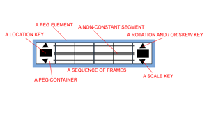
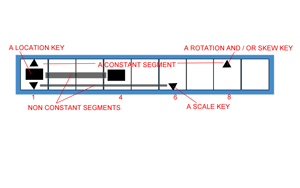
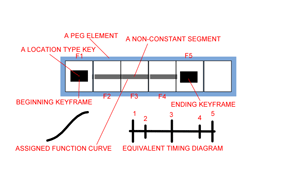
A peg, whether an independent element or integrated into a drawing or image element, can contain multiple different types of attributes of keyed frame values at each individual frame in a scene (location, scale, rotation, or skew values). TBS provides specific visual indicators on a timeline track display for each type of keyed value present at each single frame. Conceptually a peg element is a collection of pegs, each of which is a multi-valued container. Each frame position of a peg element is a peg container. For simplification we just refer to the peg element and its individual peg containers as a peg. So just like the term keyframe can be singular or plural depending on the context of our use, the same thing is true for the term peg. And a peg element can contain many connecting segments as defined by each occurrence of a starting and ending key framed value for the same type of attribute. This means that even though three segments, one for scale and one for rotation and one for location, might all start at the same frame they don’t have to be the same length, they can each end on different frames. Each segment does not have to have the same type of inbetweening method either, some could be constant and the others non-constant, and each non-constant segment has its own unique velocity function curve that controls the in between image spacing. That’s a lot of flexibility for us as animators to be able to direct.
As we learned in Part 1, key framed animation is a form of programming instructions. But in TBS we don’t write code to direct the render engine, we do it using visual tools like the scene planning tools and the function editor and the pegs themselves. How we use these visual aids dramatically effects how well we function as lead animators. So the more we understand about how they work and their interactions, the easier and more successful our directing tasks. Yes, we are animating but we are also directing the render engine and it requires significant skill and experience to do this correctly. After all we have to be the lead animator and the render engine is our obedient inbetweening assistant. That assistant does exactly what we instruct it to do, even if we inadvertently give it incorrect instructions. So it is easy to be lulled into thinking that key framed animation is really simple due to the fact that we do things visually and not by typing script code in TBS. But when you consider how detailed and complicated the directions can be which you are trying to communicate to your assistant, the render engine, you can begin to appreciate that this is not a trivial task.
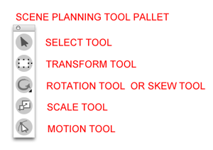
Scene planning tools
Scene planning tools are used to specify or address the type or types of attributes with which you want to work. They are more than visual manipulators, they are specific selection switches. When you select a scene planning tool from your tool pallet it becomes active and it limits what type of instructions you can influence. Once a scene planning tool has been chosen you can only create, edit, copy or delete the associated type or types of attributes of keys for that specific tool. When the transform tool is active it is used as an all purpose keying tool as it addresses location, rotation, scale and skew attributes all at the same time. When the scale tool is active it only addresses scale attribute values. When the rotation tool is active it only addresses rotation attribute values. When the skew tool is active it only addresses skew attribute values. And when the motion tool is active it only addresses motion path attribute values. The scene planning selection tool doesn't address any keyed frame types at all when it is active. But it still has an very important instructional purpose which we will learn more about in Part 3.
Each matching keyed type of attribute can be viewed as part of a pair of keyframes which is connected by an inbetweening instructional segment. Each segment is created as either a constant segment or a non-constant segment. For the same element there can be multiple types of attributes keyframed and the connecting segments for each keyframe pair of common attributes can be set independently. The way a particular keyed frame attribute is specifically addressed is by the scene planning tool you select to be active. So if you only want to address a rotation pair of keyframes you would select the rotation tool to be active. Or, if you only wanted to address a scale pair of keyframes you would select the scale tool to be active. The important concept to remember when working with keyed frame attributes is that the scene planning tool you select to be active dictates which attributes you are addressing when you are creating, editing, copying or deleting keyframes or their connecting segments. We will get into more detail about this in part 3 on Key Framed Animation.
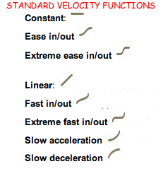
So to extend what we have learned so far, pegs are used to keyframe animate objects across time. You can attach one or more elements to a peg and you can attach pegs to other pegs to create complex hierarchies of control. Pegs are used to facilitate computer rendered inbetweening. So when you have elements attached to a peg, you can set keyframes and TBS interpolates inbetween those keyframes based on the values of those keyframes and the type of connecting segment used. And you can use velocity function curves to adjust the way the inbetweening is applied which is often called “custom easing” or "cushioning". Basically the curve specifies the rate of change between the images, their spacing.
Additionally, pegs can be controlled by motion paths which are 3D and those motion paths can have adjustable keyframes and they also can have frame independent motion control points. That allows you to have some motion control that has to happen at a specific point in time and other motion controls that are 3D space dependent and not time dependent. At this point, you should begin to see that TBS has some very sophisticated functionality that can provide a lot of flexibility for us as animators once we master the skills of directing this method of communicating instructions to the render engine.
There is a new way to use pegs in v3.5 as each image or drawing element now includes a peg as part of that image or drawing element. This means that keyframing does not require attaching elements to separate peg elements as was the case in previous TBS versions. Of course the power and flexibility of separate peg elements still exists and so this new creation of integrated peg elements is not just a simplification but is also an enhancement.
Each type of attribute of keyed frame value can be set uniquely using their own special scene planning tool. Some people misunderstand the flexibility and power of this approach. You can use the transform tool for rough keyframing and then when you go to tweak an animation action you can use the individual scene planning tools to fine tune it and not accidentally mess up other types of keyed frame attributes. Because you can individually address key framed values with specific scene planning tools on the same frame, you can selectively delete those types of key framed parameters without deleting other types of keyframed values that you want to maintain on that same frame.
Labels: Fundamentals, Key Framed Animation, Key Framing, Pegs, Scene Planning Tools, Velocity Curves


<< Home